Build Guide for CH32X-60-Improved rev2026.1
This document is a guide for soldering the CH32X-60-Improved keyboard.
Required Materials
- 1x CH32X-60-Improved PCB, preassembled with SMT components
- Available from Elecrow marketplace: CH32X-60 Improved ANSI Keyboard PCB
- 66x MX-compatible switches (5-pin)
- "5-pin" allows for the switches to be mounted to the PCB without requiring a switch plate.
- 66x MX-compatible keycaps
- Compared to a standard ANSI 60% with a 6.25u spacebar, this board replaces the 6.25u spacebar with 1× 1.25u and 5× 1u keys.
- Full count by row (top to bottom):
- Row 1 (R4): 13× 1u + 1× 2u
- Row 2 (R3): 12× 1u + 2× 1.5u
- Row 3 (R2): 11× 1u + 1× 1.75u + 1× 2.25u
- Row 4 (R1): 10× 1u + 1× 2.25u + 1× 2.75u
- Row 5 (R1, bottom): 5× 1u + 8× 1.25u (3× 1.25u left mods, 1× 1.25u + 5× 1u thumb cluster, 4× 1.25u right mods).
- 4x 2U MX stabilizers (PCB mount)
- GH-60 compatible case
- (Optional) Switch plate (1.5mm thick for MX switches)
- Switch plate is optional if using 5-pin switches.
- The SVGs for switch plates can be found on the Release page
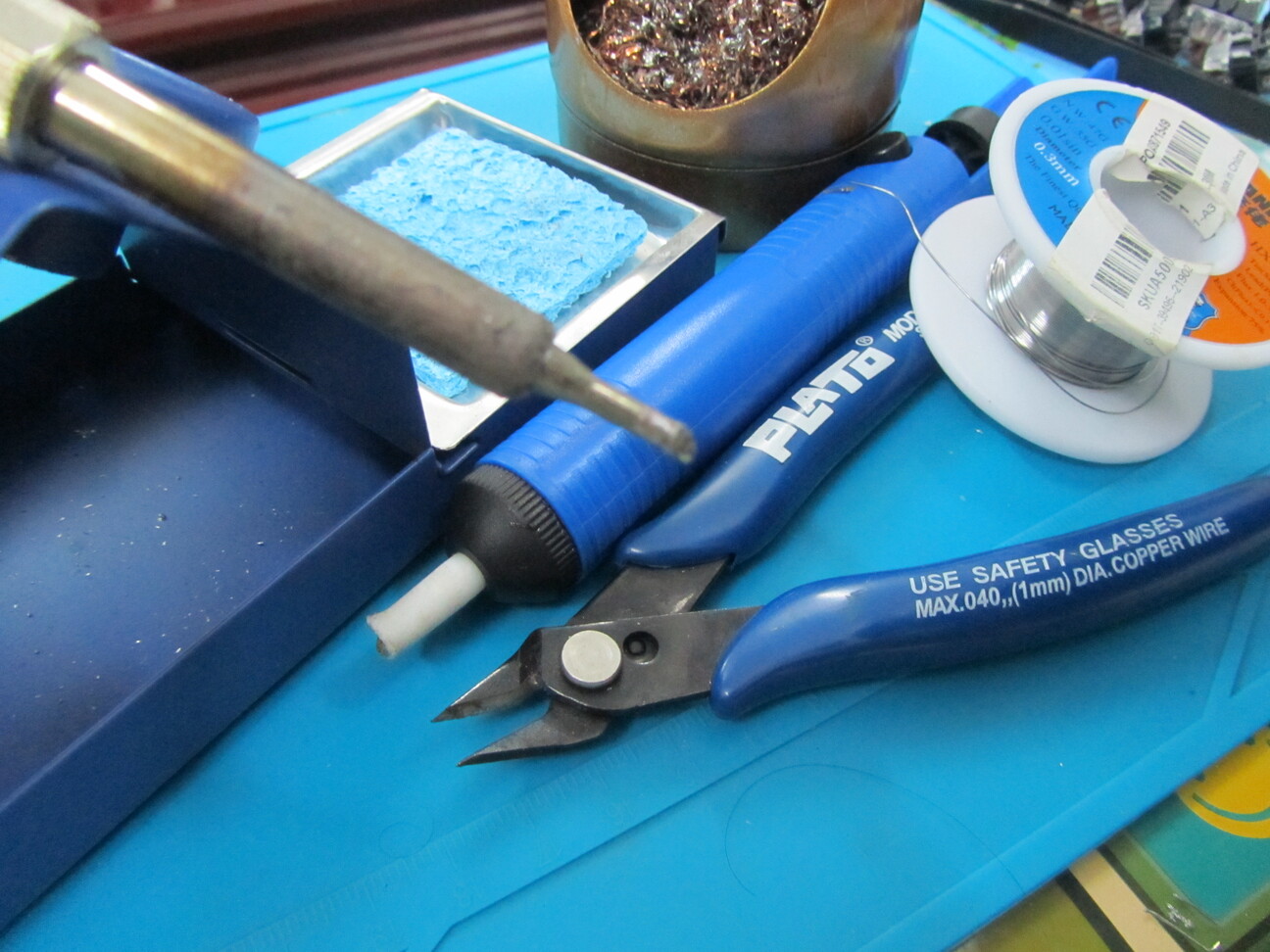
Required Soldering Tools
-
Soldering iron.
- Even a very cheap one will do.
-
Soldering iron stand.
-
Fume Extractor/Filter.
- Especially if you're soldering indoors.
-
Solder.
- I would strongly recommend using better-than-the-cheapest solder. My experience with cheap solder is that it doesn't have enough flux, which makes soldering difficult.
-
A sponge, or brass wool, for cleaning solder from the soldering iron.
-
Desoldering sucker, or desoldering wick.
- A cheap desoldering sucker should be able to do the job. However, I'd recommend getting nicer-than-cheapest because if you're using a desoldering sucker, you'll want to reduce frustration experienced. (Especially if desoldering MX keyswitches).
-
Flush cutters.
-
Soldering mat; or cardboard or whatever to protect the surface from damage while soldering.
Recommended Tools
-
Digital Mulitmeter.
- The most useful functionality here is the continuity check.
- Take care, most cheap multimeters don't switch off automatically, which results in the battery draining completely after use if the multimeter isn't switched off.
-
Bevel/chisel soldering iron tip.
- Not strictly necessary, but it's what I used in this build.
-
Needle-nosed pliers.
-
Tweezers.
-
Wire stripper / Jumper wire.
- In many cases, jumper wire can be used to 'repair' a connection between keyboard switches, or fix other small mistakes/damages.
Nice to Have
-
Twin-Headed Soldering Iron
- If you're going to do a lot of soldering of SMD diodes/resistors/etc., then it's very useful to have twin-headed soldering tweezers.
-
Hot Air Gun
- Makes it easier to solder SMD components.
Flash Firmware and Check PCB Works
Before soldering the switches, you can flash the PCB with firmware and check that the PCB works.
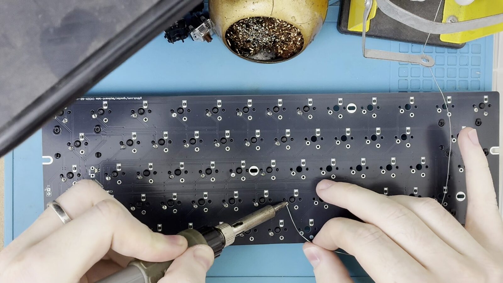
You can download a precompiled firmware binary from the releases page, then use tweezers or a paperclip to short the switch pads (connect the plated circular through-holes together).
Shorting the switch pads together is like pressing the switch, so you can visit a keyboard testing website and check each key works.
You can be confident the keyboard works if every key in any column works, and every key in any row works. That is, you don't need to check all 66 keys, you only need to check one row and one column.
Flashing Instructions
WCH ISP Programs
Official WCH ISP Tool
You can flash firmware onto the keyboards with the CH32X0 using WCH's WCH ISP tool.
https://www.wch-ic.com/downloads/WCHISPTool_Setup_exe.html
Open Source wch command line tools
There are several open source programs which can be used.
I like the Rust wchisp command line tool.
(https://github.com/ch32-rs/wchisp).
Be sure to read the notes on the readme
(e.g. installation requirements for Windows/Linux/etc.).
With wchisp, you enter the bootloader and then run:
wchisp flash <my firmware.hex>
Entering the Bootloader
There are different ways to enter bootloader mode.
Shorting BOOT/DOWNLOAD and Plugging in USB
WCH's CH32X0 MCUs have a bootloader which runs in bootloader mode when the USB is plugged in with BOOT shorted.
On the PCBs in this repository, the pads to short together are labelled with "BOOT".
This bootloader is read-only, so you will always be able to enter the bootloader using this method.
The steps to flash with this method are:
-
Short the BOOT pads together (e.g. using a paperclip or tweezers to connect the two BOOT pads together).
-
Connect the keyboard to the computer.
-
Flash the firmware using whichever WCH ISP tool you're using.
smart-keymap Firmware: Hold Down the First Key
For keyboard firmware built with the smart-keymap firmware,
the firmware will enter the bootloader if the key SW_1_1
is held when the USB is connected.
This works if the correct keyboard firmware has been flashed.
The steps to flash with this method are:
-
With a keyboard running the smart-keymap firmware, hold down the switch at the top left (
SW_1_1). -
Connect the keyboard to the computer.
-
Flash the firmware using whichever WCH ISP tool you're using.
smart-keymap Firmware: BOOT Key
For keyboard firmware built with the smart-keymap firmware,
the firmware will enter the bootloader
when the K.BOOT/K.reset_to_bootloader key is pressed.
The steps to flash with this method are:
-
With a keyboard running the smart-keymap firmware, and with the keyboard connected to the computer: tap the
K.BOOTkey. -
Flash the firmware using whichever WCH ISP tool you're using.
Help, I Bricked my Keyboard
Because the USB bootloader is in the CH32X0's ROM, it's practically impossible to brick the keyboard. You'll always be able to flash new firmware by shorting BOOT/DOWNLOAD and plugging in USB.
Build Guide
The soldering required for this keyboard is very simple.
-
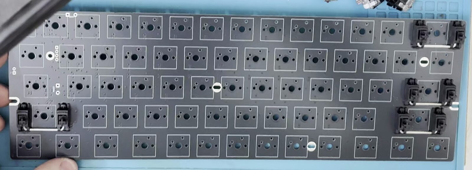
Mount all 4 of the 2U stabilizers on the PCB.
-
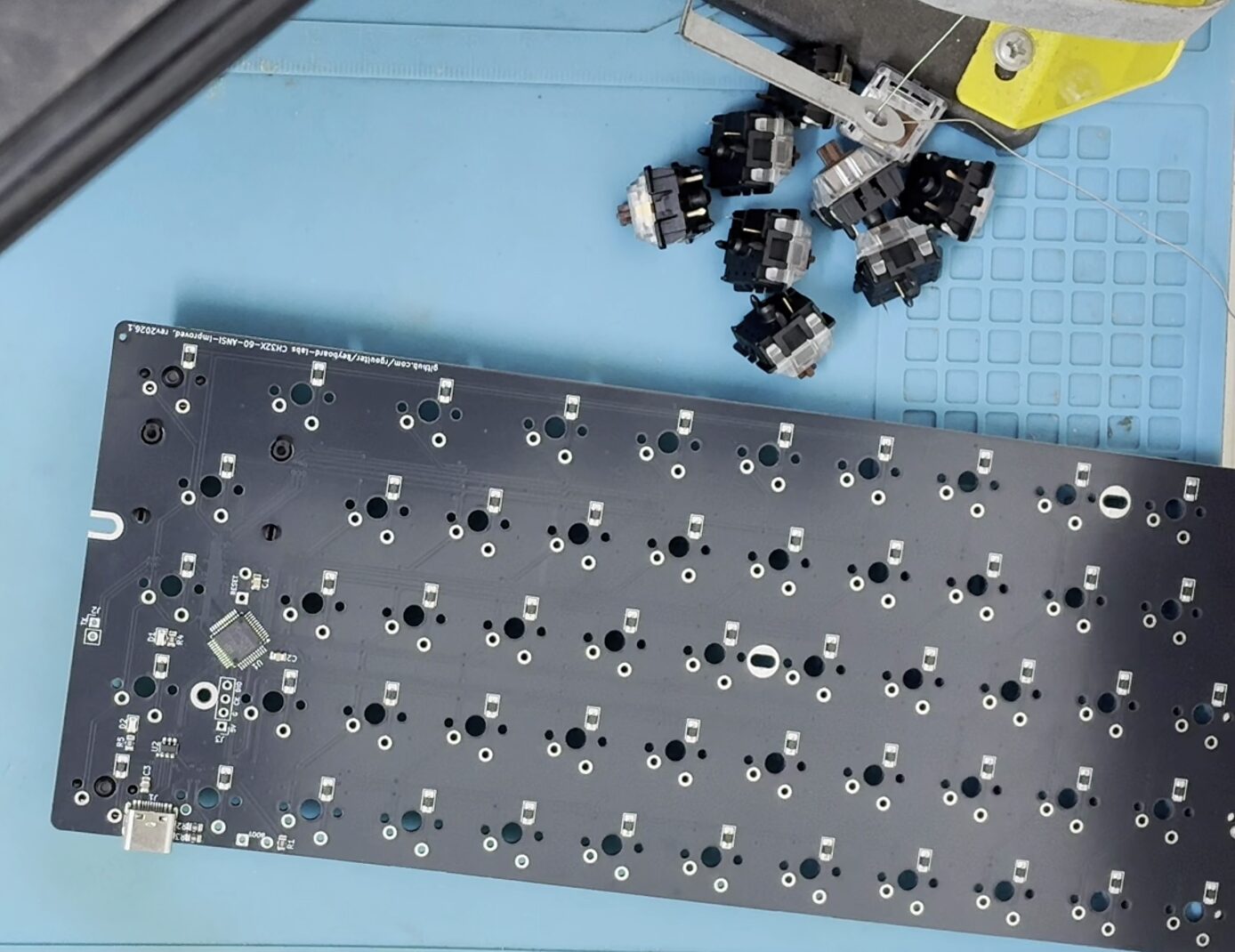
If you're using a switch plate, arrange the plate and place some switches before soldering.
It can help to solder just the four corner switches first to hold the plate in place.
-
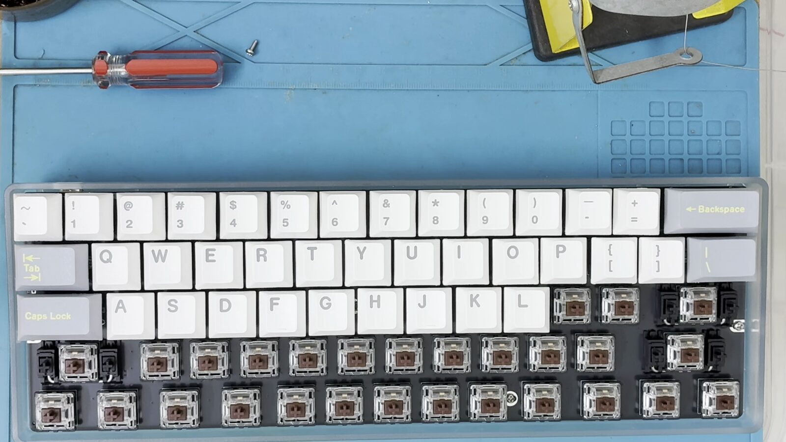
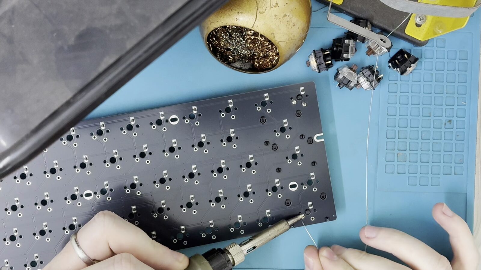
Solder the switches.
If not using a switch plate, I recommend soldering just one pad of each switch first, then checking that the switch is sitting flush on the PCB (heat the solder and push the switch against the PCB; then remove the iron from the solder, and then stop pushing the switch). It's easier to correctly align the switches if only one of its pads soldered.
A switch plate is entirely optional, and with 5-pin switches the plate is not needed to hold the switches.
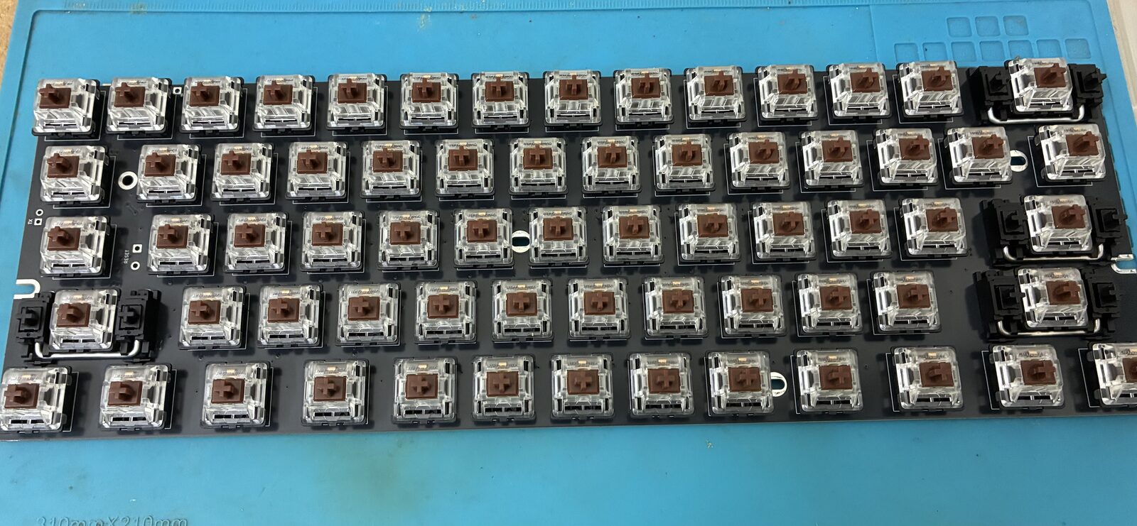
Either way, I think it's easiest to start by soldering the switches in the corners:
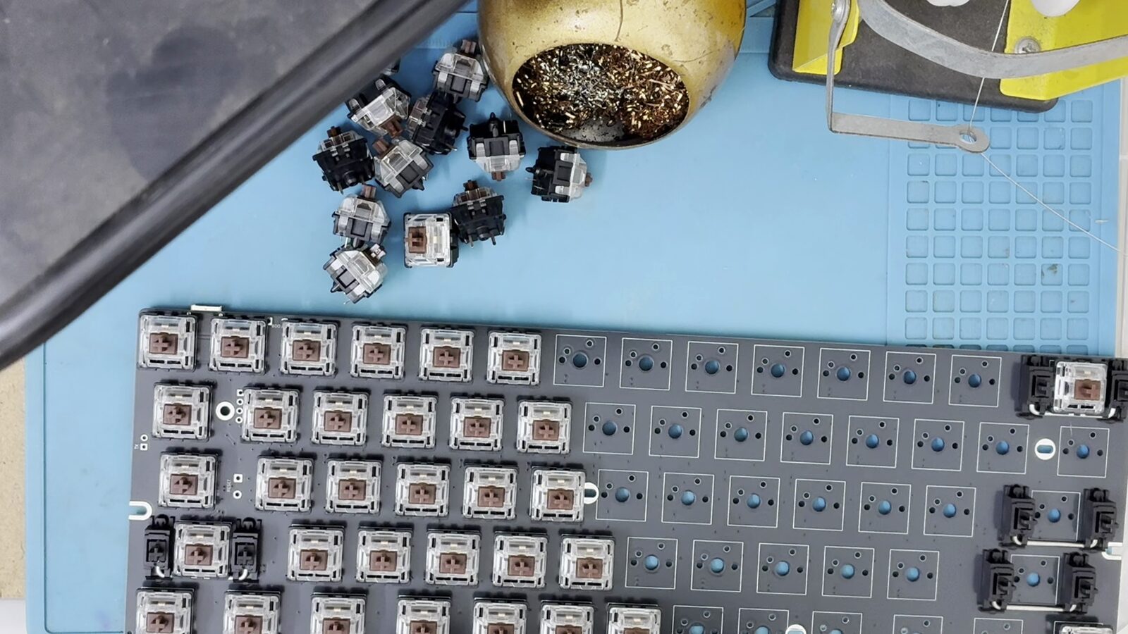
Continue placing & soldering switches until you're done:
If you didn't flash the firmware before, you'll want to flash the firmware before assembling it into the case, since the keyboard PCB's BOOT pads can be a bit cumbersome to access when it's in the case.
Ensure that you've soldered the switch to both pads for all of the switches.
-
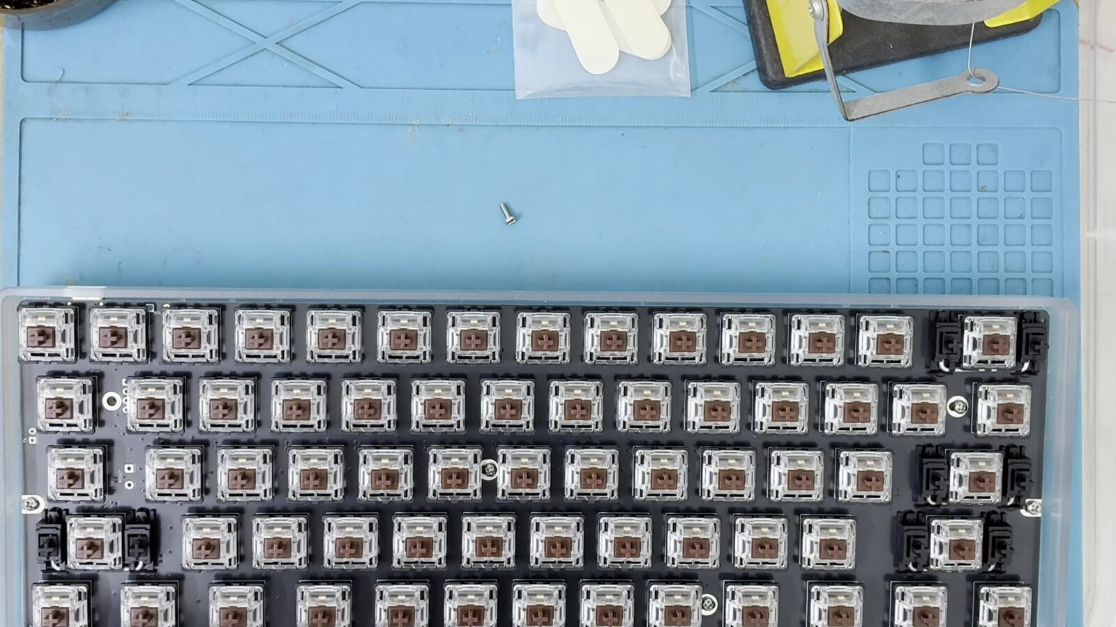
Assemble the keyboard into the case.
-
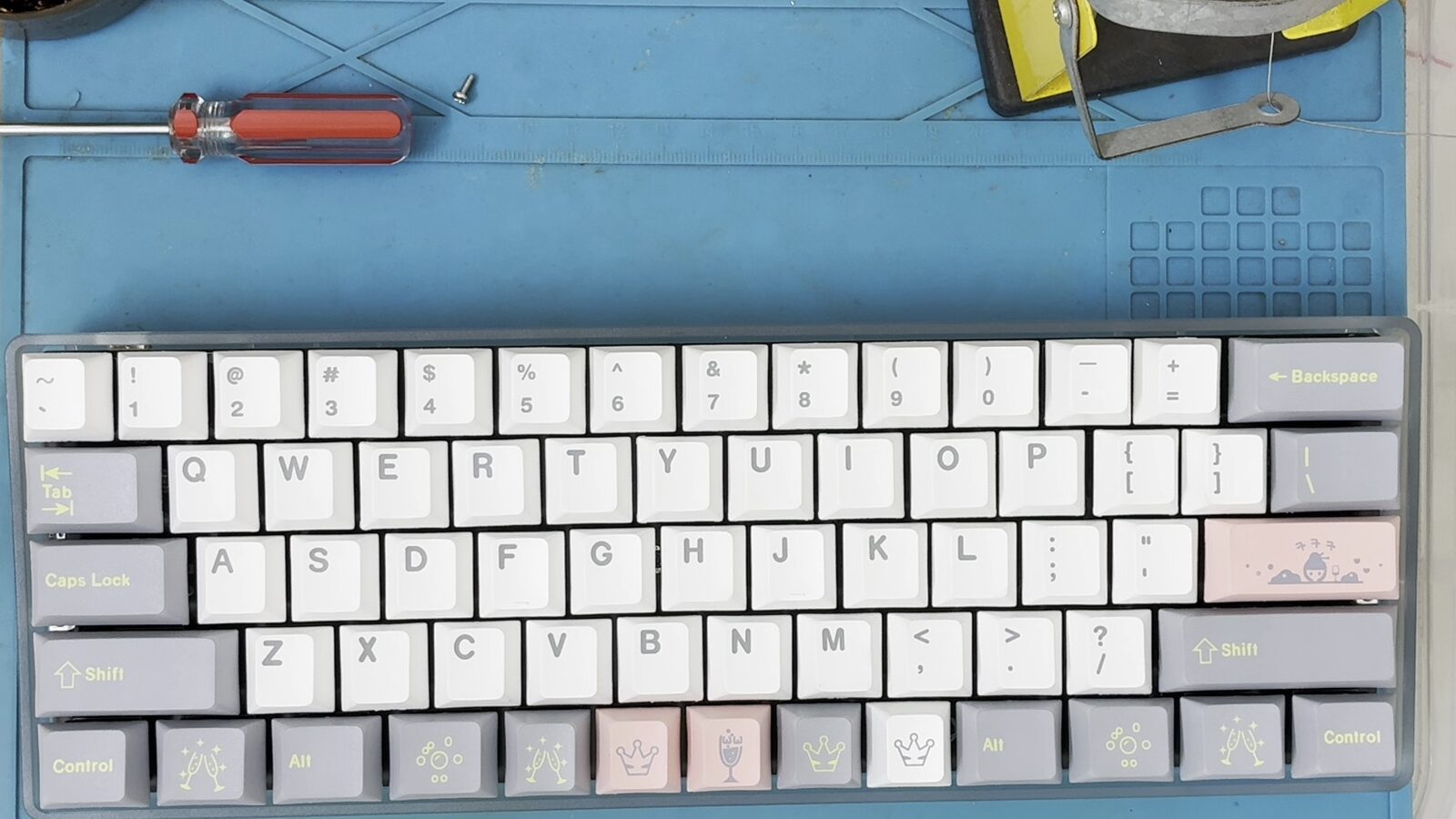
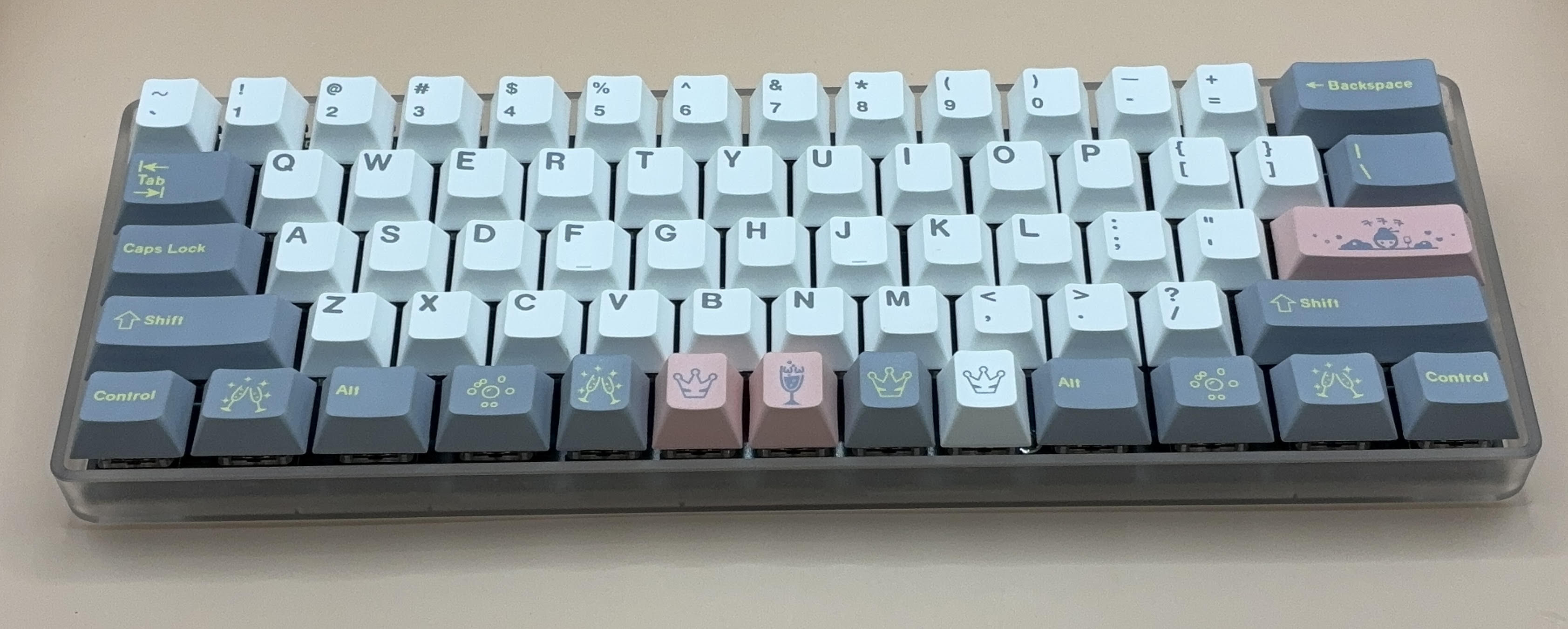
Place the keycaps.