Many hobbyist keyboard PCBs make use of RGB LEDs. The most common kind I've seen are WS2812 (or are compatible with WS2812, e.g. SK6812 5050 or SK6812mini-e (or sometimes SK6812mini 3535)).
Most hobbyist keyboard PCBs I've seen also make use of the Pro Micro development board.
Loosely, the WS2812 LEDs require there data signal is 5V.
This isn't a problem for the Pro Micro (which uses 5V for its
GPIO pads).
But because the MiniF4 "Black Pill" development board's GPIO
pads are 3.3V, the signal from the GPIO needs its logic level shifted
for the WS2812 RGB LEDs to work.
A couple of examples of ways to do this:
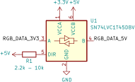
Use a Logic-Level Shifting IC
e.g. using an SN74LVC1T45DBV:
Use a MOSFET
e.g. this StackOverflow answer[0] gives the following schematic:
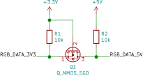
This answer to a similar question[1] provides more discussion as to how the circuit works.
See also e.g. SparkFun's tutorial on transistors[2].
References
[0] https://electronics.stackexchange.com/questions/245925/5v-to-3-3v-level-shifting-circuit