Build Guide for Pico42 rev2023.1
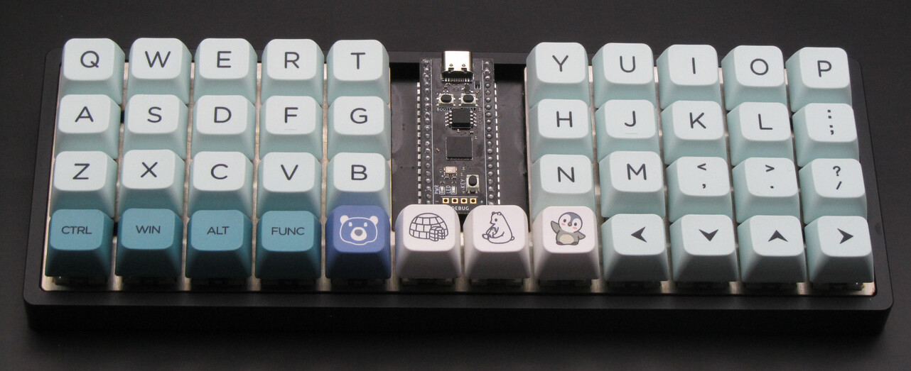
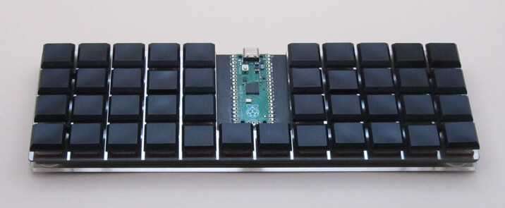
This document is a guide for soldering the Pico42 keyboard.
Required Materials
- 1x PCB
- 1x Raspberry Pi "Pico" development board
- 42x MX-compatible switches, or Kailh Choc v1 switches.
- (Optional) Socketing headers:
- 1x 1x40 SIP round-pin male headers,
- 1x 1x40 SIP round-pin female header sockets.
- Switch plate (1.5mm thick for MX switches, 1.0mm thick for Choc switches)
- Switch plate is optional if using 5-pin switches.
- Case or bottom plate.
- M2 screws, for mounting PCB to the case.
- e.g. for sandwich style (switch plate + bottom plate):
- 4x PM M2x3mm screws
- 5x PM M2x5mm screws
- 5x M2 4mm brass female-female spacers
Required Soldering Tools
-
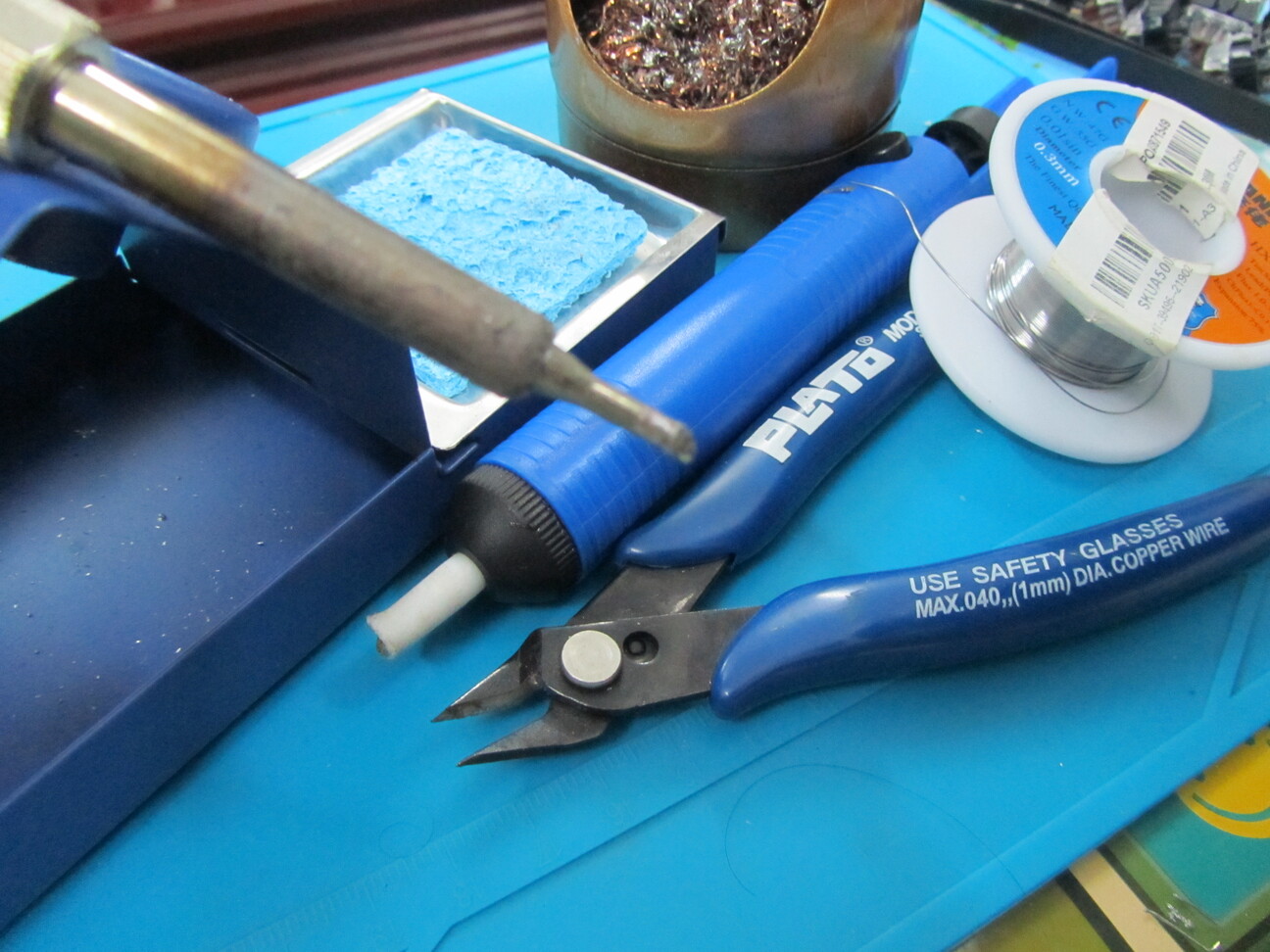
Soldering iron.
- Even a very cheap one will do.
-
Soldering iron stand.
-
Fume Extractor/Filter.
- Especially if you're soldering indoors.
-
Solder.
- I would strongly recommend using better-than-the-cheapest solder. My experience with cheap solder is that it doesn't have enough flux, which makes soldering difficult.
-
A sponge, or brass wool, for cleaning solder from the soldering iron.
-
Desoldering sucker, or desoldering wick.
- A cheap desoldering sucker should be able to do the job. However, I'd recommend getting nicer-than-cheapest because if you're using a desoldering sucker, you'll want to reduce frustration experienced. (Especially if desoldering MX keyswitches).
-
Flush cutters.
-
Soldering mat; or cardboard or whatever to protect the surface from damage while soldering.
Recommended Tools
-
Digital Mulitmeter.
- The most useful functionality here is the continuity check.
- Take care, most cheap multimeters don't switch off automatically, which results in the battery draining completely after use if the multimeter isn't switched off.
-
Bevel/chisel soldering iron tip.
- Not strictly necessary, but it's what I used in this build.
-
Needle-nosed pliers.
-
Tweezers.
-
Wire stripper / Jumper wire.
- In many cases, jumper wire can be used to 'repair' a connection between keyboard switches, or fix other small mistakes/damages.
Nice to Have
-
Twin-Headed Soldering Iron
- If you're going to do a lot of soldering of SMD diodes/resistors/etc., then it's very useful to have twin-headed soldering tweezers.
-
Hot Air Gun
- Makes it easier to solder SMD components.
Build Guide
The soldering required for this keyboard is very simple. (Simpler than soldering practice kits).
-
Solder the diodes for the switches.
-
Solder the dev board (and whatever headers for the dev board).
-
Using the switch plate to align the switches, solder the switches in.
Notes
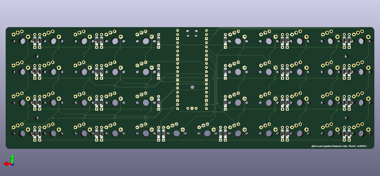
- Diode direction: the cathode (negative, marked side) should be soldered towards the through-hole pad which is shaped like a square.
- Mounting the dev board:
- Since the Pico has castellated edges, the dev board can be soldered directly to the Pico42 PCB.
- The Pico can also be soldered onto headers, which allows
the dev board to sit higher.
- By socketing the dev-board using round-pin male headers, and round-pin female headers, the dev board still is below the height of MX switches, but sits high enough to mount the PCB in the low-profile JJ40 case.
- Socketing also allows easily removing/replacing the dev board.
Flashing the Pico
You can enter the bootloader on the Raspberry Pi Pico (which shows a drive labelled "RPI-RP2") by holding the BOOTSEL button when connecting the dev board to the computer.
The UF2 file for the firmware (e.g. CircuitPython for KMK, or the UF2 from QMK) can then be copy-pasted onto this drive.
One of the nice things about the RP2040 chip is that it natively supports flashing its firmware with UF2. This saves the trouble of having to flash a custom bootloader onto the chip.
The RP2040 chip is also powerful enough to run Circuit Python, and thus run KMK firmware[0]. Since KMK runs using Circuit Python, updating/changing keyboard maps written for KMK is as easy as editing files on a USB flash drive.
Using KMK as the Keyboard Firmware
For running KMK, the RP2040 needs to be running Circuit Python firmware for the appropriate board. e.g. Circuit Python for JPConstantineau's PyKey60 board[1]. -- This can be flashed to the RP2040 by making it enter its bootloader, then copying the UF2 file to the RP2040 drive.
With Circuit Python running on the RP2040, setting up KMK involves copying the
kmk directory from the kmk_firmware repository onto the device, etc., as
explained in KMK's Getting Started
docs[3].
-- Once it has been set up, changing the keyboard's keymap involves simply
changing the code.py on the CIRCUITPY volume.
For convenience, you might want to use the BOOTLOADER
key[4]
to enter the bootloader, if you want to be able to change the UF2 bootloader
frequently. (If you plan on using KMK, you probably don't).
Using QMK as the Keyboard Firmware
When using QMK, you need to compile the firmware each time you want to change the keymap.
The QMK documentation has notes on flashing for the
RP2040[4]. e.g. You
can use its QK_BOOT keycode as a way of selecting a bootloader.
The QMK documentation has notes on RP2040 specific details, too.
Entering Bootloader via Hardware
e.g. the PyKey40 has BOOT and RST on the PCB. To enter the bootloader, short
(e.g. with a pair of tweezers) the BOOT pads, and then short the RST pads.
References
[0] https://github.com/KMKfw/kmk_firmware/
[1] https://circuitpython.org/board/jpconstantineau_pykey60/
[2] https://github.com/KMKfw/kmk_firmware/blob/master/docs/en/Getting_Started.md
[3] https://github.com/KMKfw/kmk_firmware/blob/74677e28fac18281307d6e4436126472e956a75e/kmk/keys.py#L369
[4] https://docs.qmk.fm/#/flashing?id=raspberry-pi-rp2040-uf2